The platform
One host board and the satellites that plug into it
Every entry links to its schematic, KiCad project, gerbers, BOM and pinout. These are the Rev-B boards, the ones the campaign ships. The first run arrived on 28 October and bring-up has been running since: six of these boards have had a test pass on them, two are on the bench untouched, and three were drawn after the order went in. The badge on each says which, and nothing here claims a measurement that has not been taken.
- Verified a bring-up test passed on it
- Built, untested on the bench, nothing proven yet
- Designed drawn and routed, never ordered
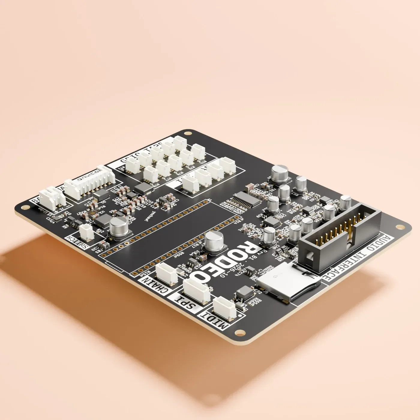
rodeo-motherboard
VerifiedThe motherboard has one job: carry the Daisy, the audio, and the connectors everything else plugs into. There are no converters on it: those pins drive a second codec instead, and high-resolution analog moved to an optional expander board. Controls no longer compete for motherboard channels, because the satellite chain grows by adding satellites. It also carries the battery, its charger and a fuel gauge, so the instrument charges over USB-C and runs off the desk.
- audio
- 4 in / 4 out, both codecs in one callback
- general-purpose I/O
- 10 connectors, 8 analog-capable
- control growth
- satellite chain on USART3
- I²C
- 4 taps, pull-ups on board
- storage
- internal SD — 1.24 MB/s read, measured
- USB
- audio, MIDI, serial and disk mode, all on the USB-C
- MIDI
- on a daughterboard
- power
- 1S Li-ion, charger and fuel gauge
- expansion
- SPI header, looped byte-exact to 6.2 Mbit/s
It boots. The Seed came up on this board on 2026-10-28, and nine of the eleven bring-up tests have passed on it since: both codecs, MIDI, the I/O connectors, the satellite chain, the SD card, USB-MIDI, disk mode, USB audio and the SPI header. Only the OLED test has not been run.
The battery gauge on the board we have is dead, and that is our fault: J1’s pin order is the reverse of every cell in the building, the first one went in backwards and the board got very hot. The MAX17048 has answered on I²C with 0 V ever since. The next revision swaps J1 and adds the reverse protection B1 went without.
The second codec’s ADC takes corrupted samples whenever its own DAC is playing — a layout fault, SDOUT running 0.15 mm alongside SDIN and SCLK for about 50 mm. Sending the DAC 16-bit words cuts it roughly a hundredfold, which is why USB audio defaults to 16-bit. The next revision moves the trace and adds series resistors.
No on-board ADCs. The two ADS114S08s, their 24 pot connectors and the pull-downs are removed; that bank becomes an optional expander on the SPI header.
The satellites
Four controls at a time, or one
Each satellite reads its own controls and passes them along a chain. The last one closes the ring by itself, and a satellite’s position in the chain is its address — so growing a panel means plugging in another board, never respinning the motherboard. The banks put four controls on a 25 mm grid; the singles are for the knob that does not belong in a row.
-
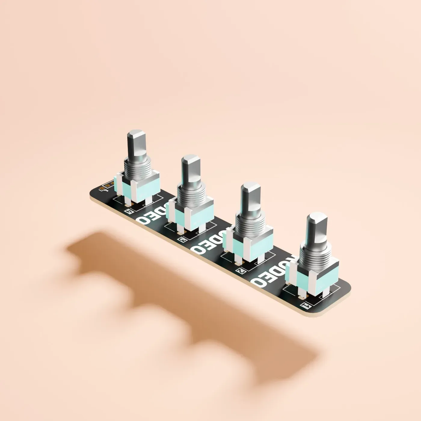
Rev-B · CAD render rodeo-pot-bank-4
VerifiedFour 9 mm pots on 25 mm centres, read by one CH32V003 on the chain.
- controls
- 4 × 9 mm pot, 25 mm centres
- outline
- 20 × 100 mm
-
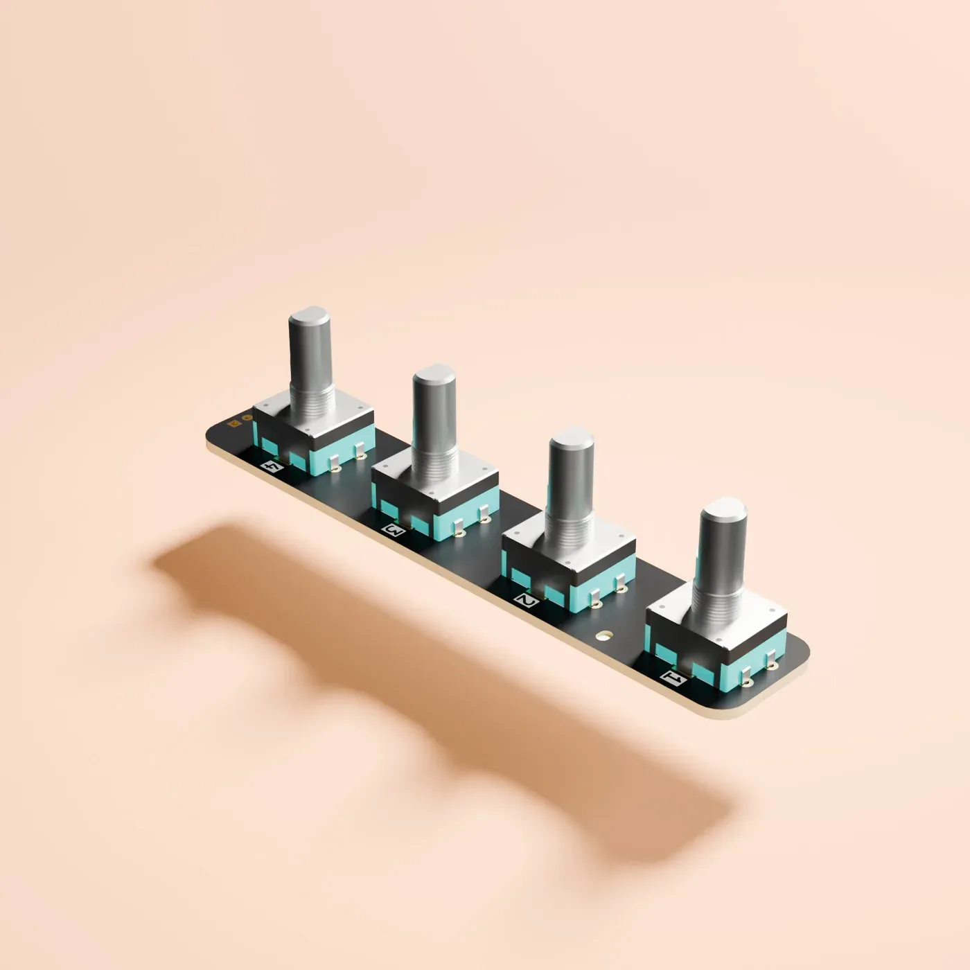
Rev-B · CAD render rodeo-encoder-bank-4
VerifiedFour 12 mm encoders with push switches, built to sit beside the pot bank.
- controls
- 4 × 12 mm encoder with switch
- outline
- 20 × 100 mm, matching the pot bank
-
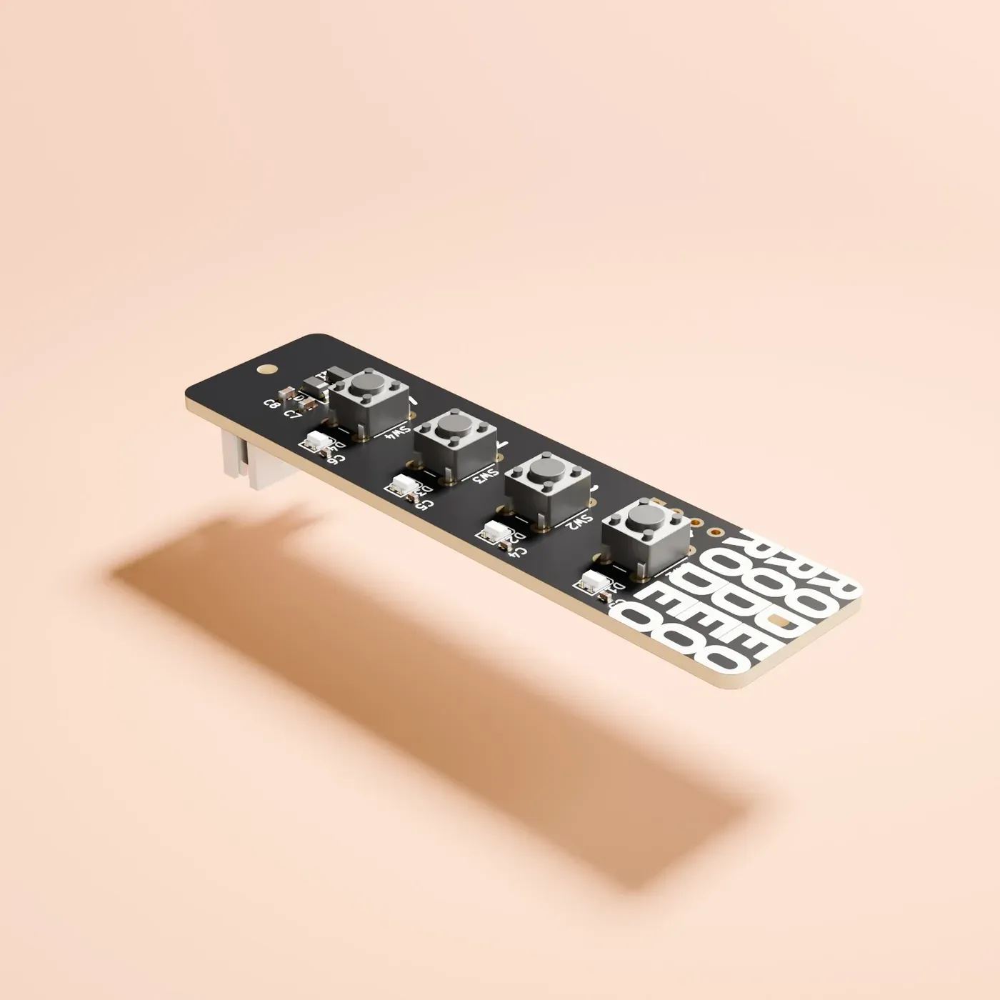
Rev-B · CAD render rodeo-button-bank-4
DesignedFour buttons on 12.5 mm centres, each with an addressable RGB LED beside it.
- controls
- 4 × tact switch, 12.5 mm centres
- indicators
- 4 × WS2812B addressable RGB
-
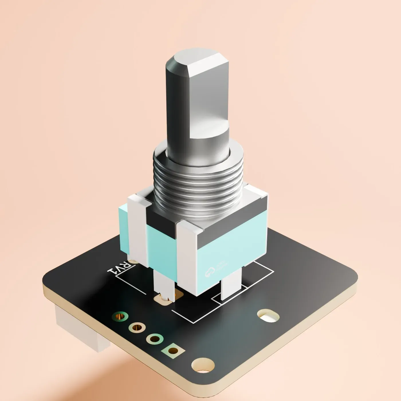
Rev-B · CAD render rodeo-pot-1
DesignedOne 9 mm pot on the chain, for a knob that does not belong in a row of four.
- controls
- 1 × 9 mm pot, panel mount
- outline
- 25 × 25 mm
-
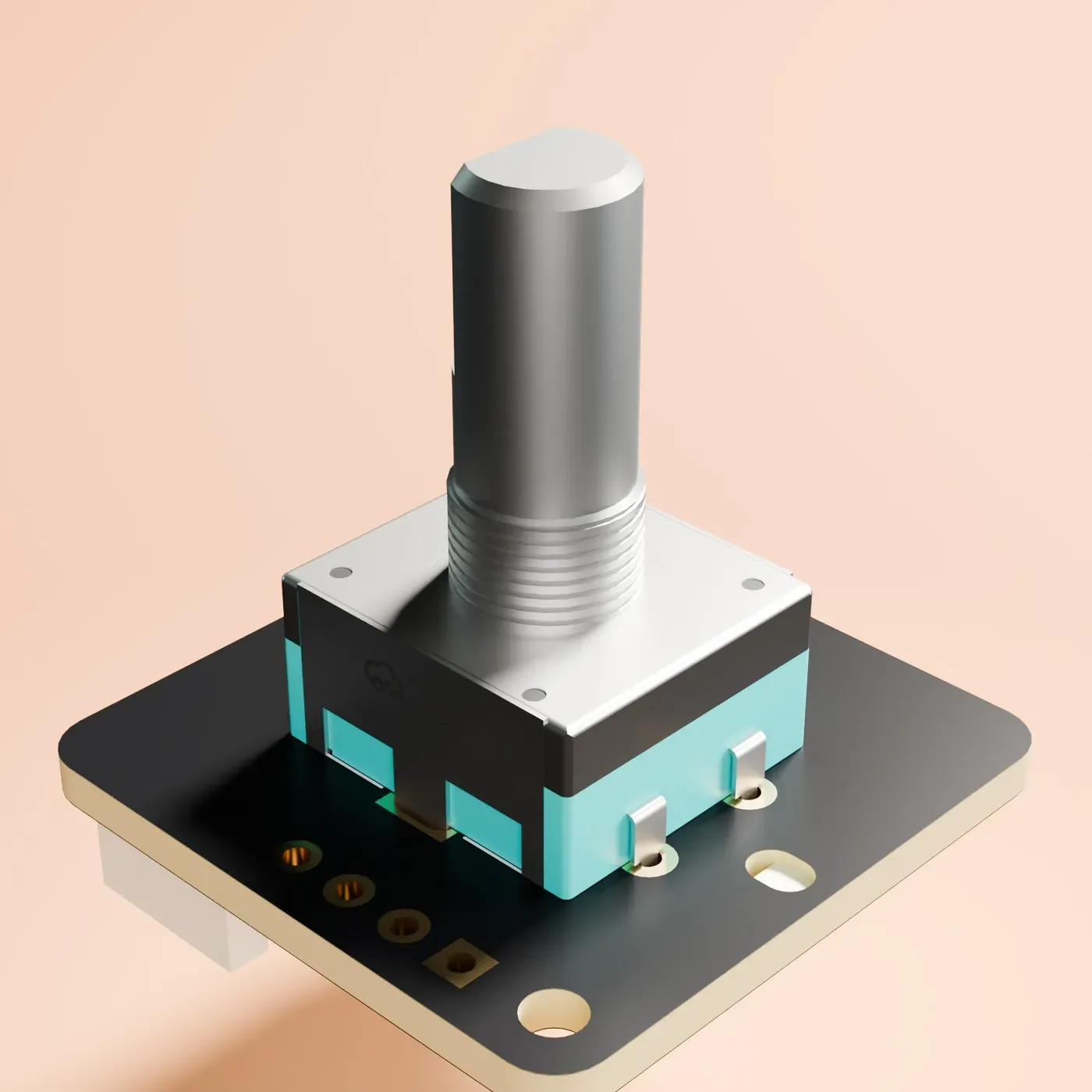
Rev-B · CAD render rodeo-encoder-1
DesignedOne 12 mm encoder with a push switch, on the single pot’s footprint.
- controls
- 1 × 12 mm encoder with push switch
- outline
- 25 × 25 mm, the single pot’s
The daughterboards
Everything that reaches the outside world
Jacks, power and MIDI leave the motherboard in Rev-B and bolt to the rear rail. It keeps the host board smaller, and it means the connectors a build does not need are connectors it does not pay for.
-
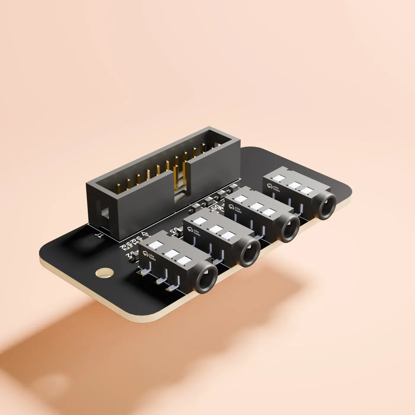
Rev-B · CAD render rodeo-audio-3.5mm
VerifiedFour stereo 3.5 mm jacks carrying the motherboard’s eight audio signals.
- jacks
- 4 × stereo 3.5 mm TRS
- carries
- the 8 audio signals on the 2×10 ribbon
-
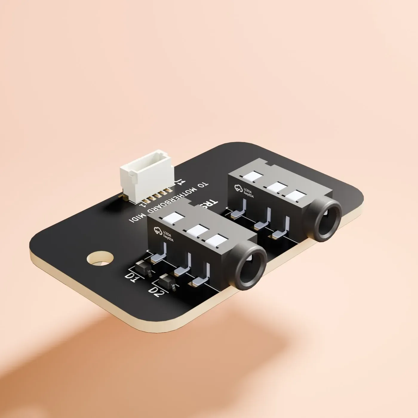
Rev-B · CAD render rodeo-midi
VerifiedMIDI in and out on TRS Type A, on the back panel.
- jacks
- 2 × 3.5 mm TRS Type A, in and out
- to the motherboard
- JST SH 5-pin, pin for pin with J6
-
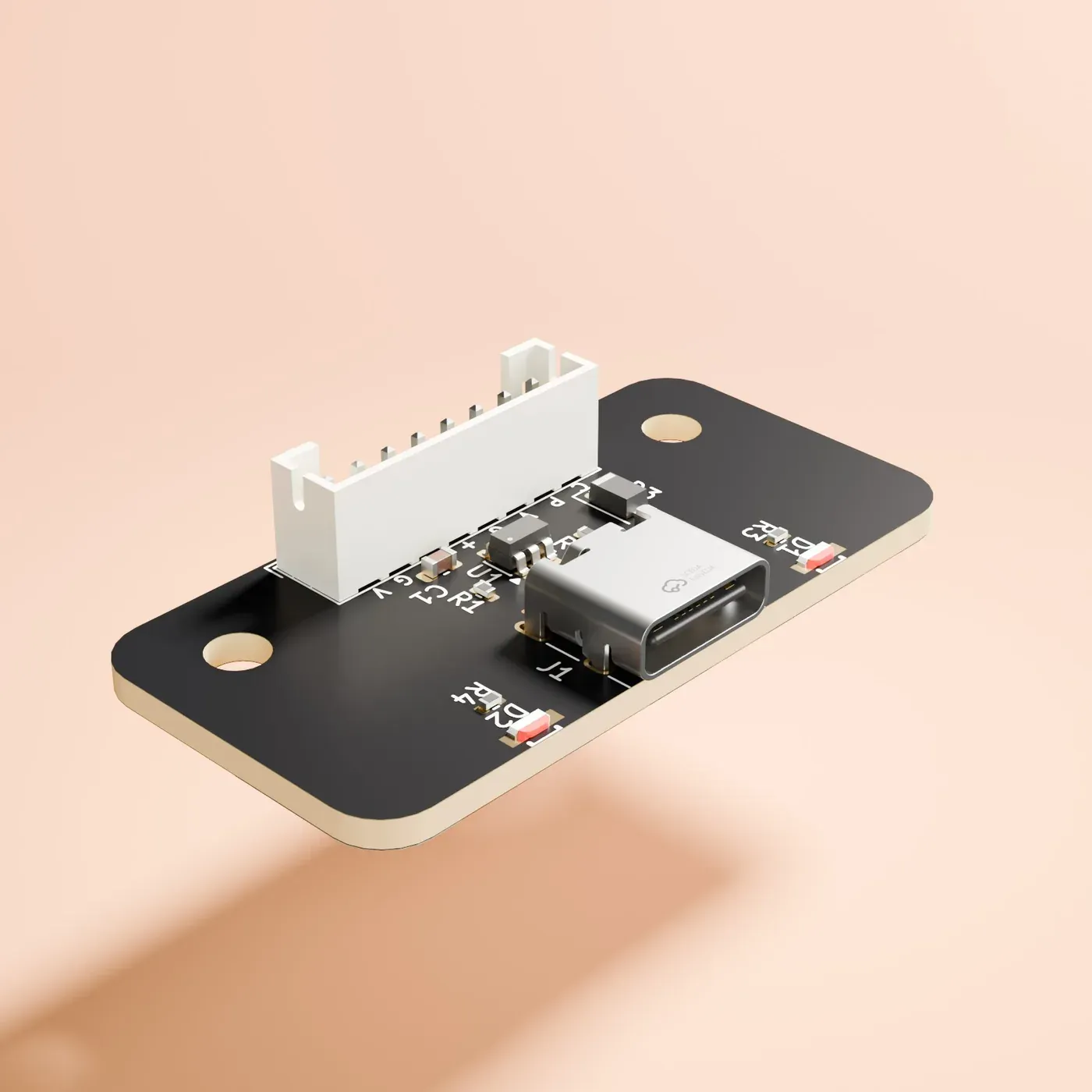
Rev-B · CAD render rodeo-power-usbc
VerifiedThe default power input, and the board that carries USB data to the Seed.
- input
- USB-C, 5 V sink, no USB-PD
- also carries
- USB data for the Seed, and status LEDs
-
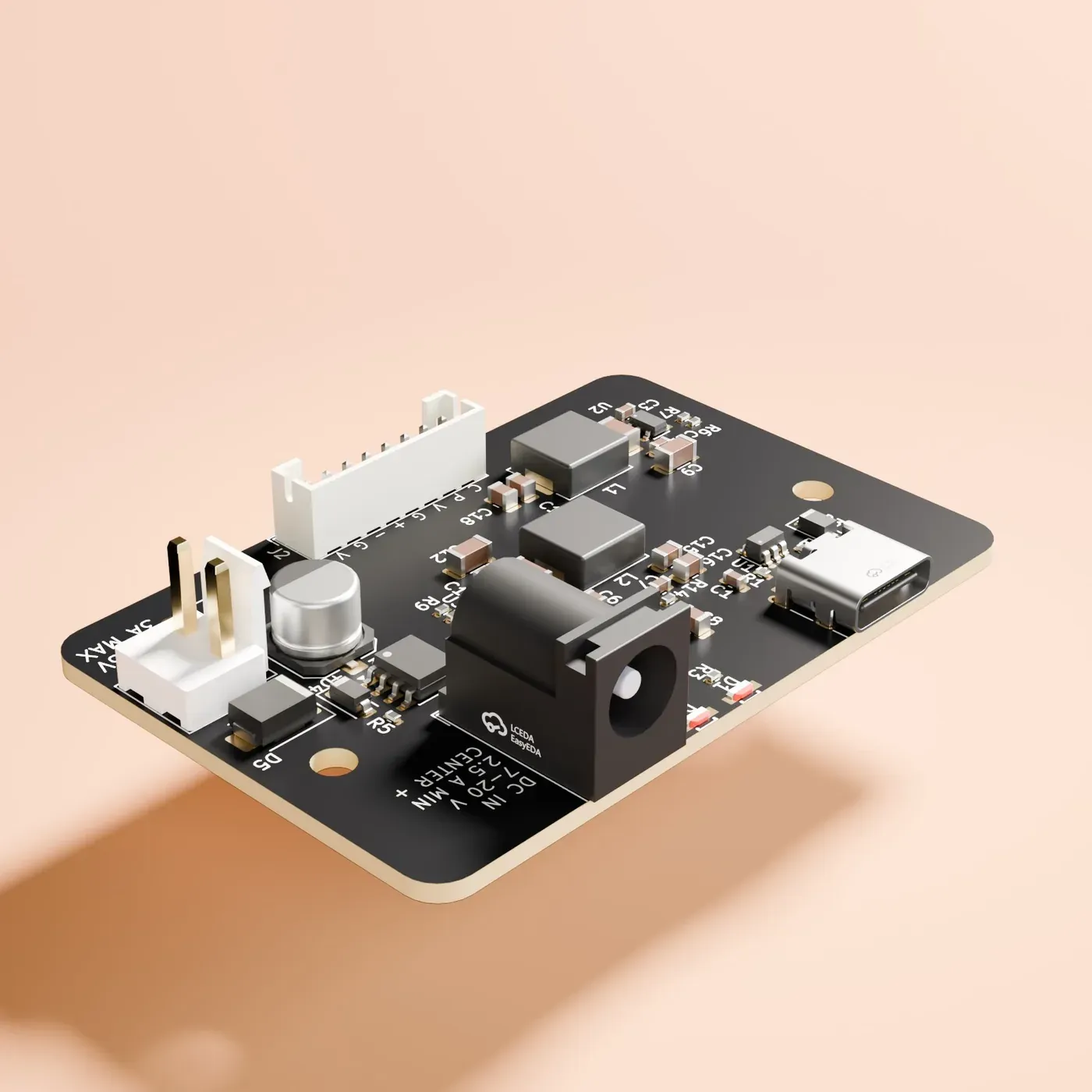
Rev-B · CAD render rodeo-power-barrel
Built, untestedThe USB-C board plus a barrel jack and a separate 5 V output for LED strips.
- adapter
- 5.5 × 2.1 mm, centre positive, 7–20 V
- switchover
- barrel takes priority, USB is the fallback
-
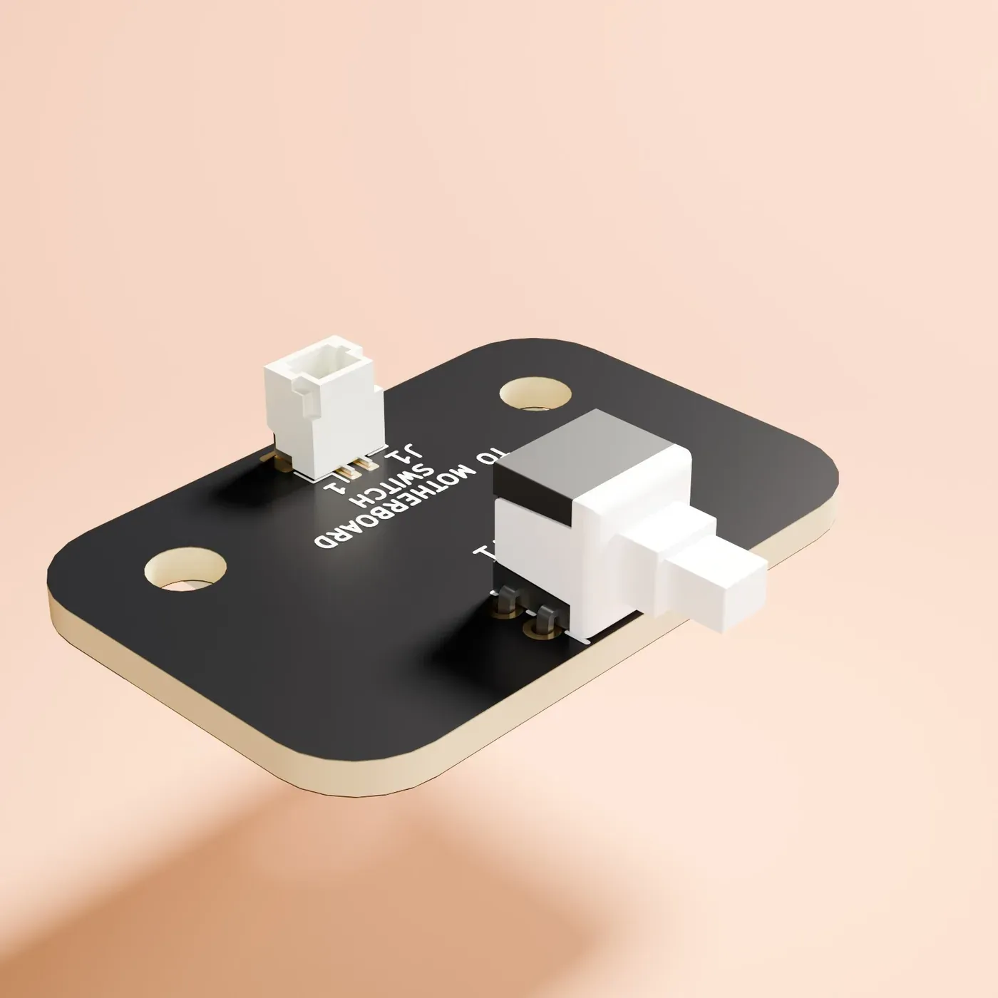
Rev-B · CAD render rodeo-power-switch
Built, untestedA latching button on the back panel that turns the synth off without stopping the charge.
- switch
- latching push button, panel mount
- to the motherboard
- JST SH 2-pin on J3
Build one?
Rodeo goes to Kickstarter in January 2027. Join the waitlist to hear first, and to watch these boards come back from the fab.