The prototype
Rev-AThe board that proved it
Rev-A exists. It was fabricated, assembled and run, and everything on this page was measured on it rather than designed into a schematic. It is also not what the campaign ships — the boards in these photographs taught us enough to change the architecture, and Rev-B is the result.
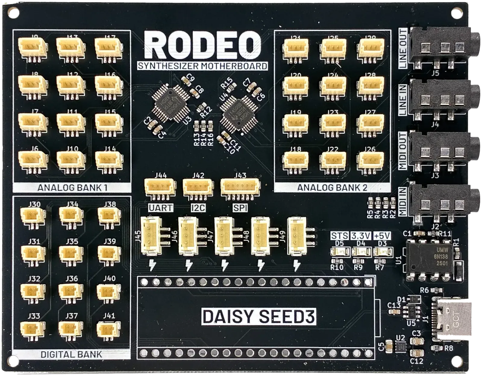
Measured, not designed
What it proved
The reason to trust a platform that has not shipped yet is what its prototype did on a bench. Every line below happened on the hardware in these photographs.
- analog in
- 24 channels, 16-bit
- conversion path
- bench-confirmed on silicon, 2026-08-14
- digital in
- 12 raw Daisy GPIO
- audio
- line in and out, 3.5 mm
- MIDI
- in and out, TRS
- control bus
- I²C
- encoder hub
- 9 encoders on one I²C target
- hub firmware
- running on a fabbed board, 2026-09-12
- register contract
- silicon-verified, 2026-08-20
- host
- Daisy Seed3, 40-pin footprint
The panel USB-C is power only. The Seed’s USB data lines dead-end at pins 37/36, so there is no USB-MIDI, no USB audio and no flashing over the panel connector.
The encoder hub carries the only I²C pull-ups on the bus, so the host needs a hub present for I²C to work at all. A blank display with no hub attached is a missing-pull-up symptom, not firmware.
The hardware
Rev-A in the flesh
-
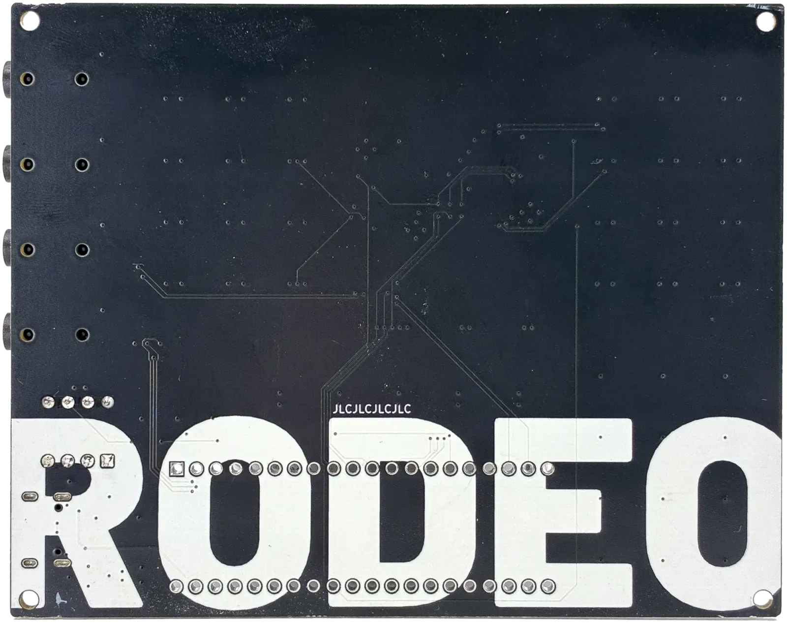
Prototype— the same board, reverse · photo -
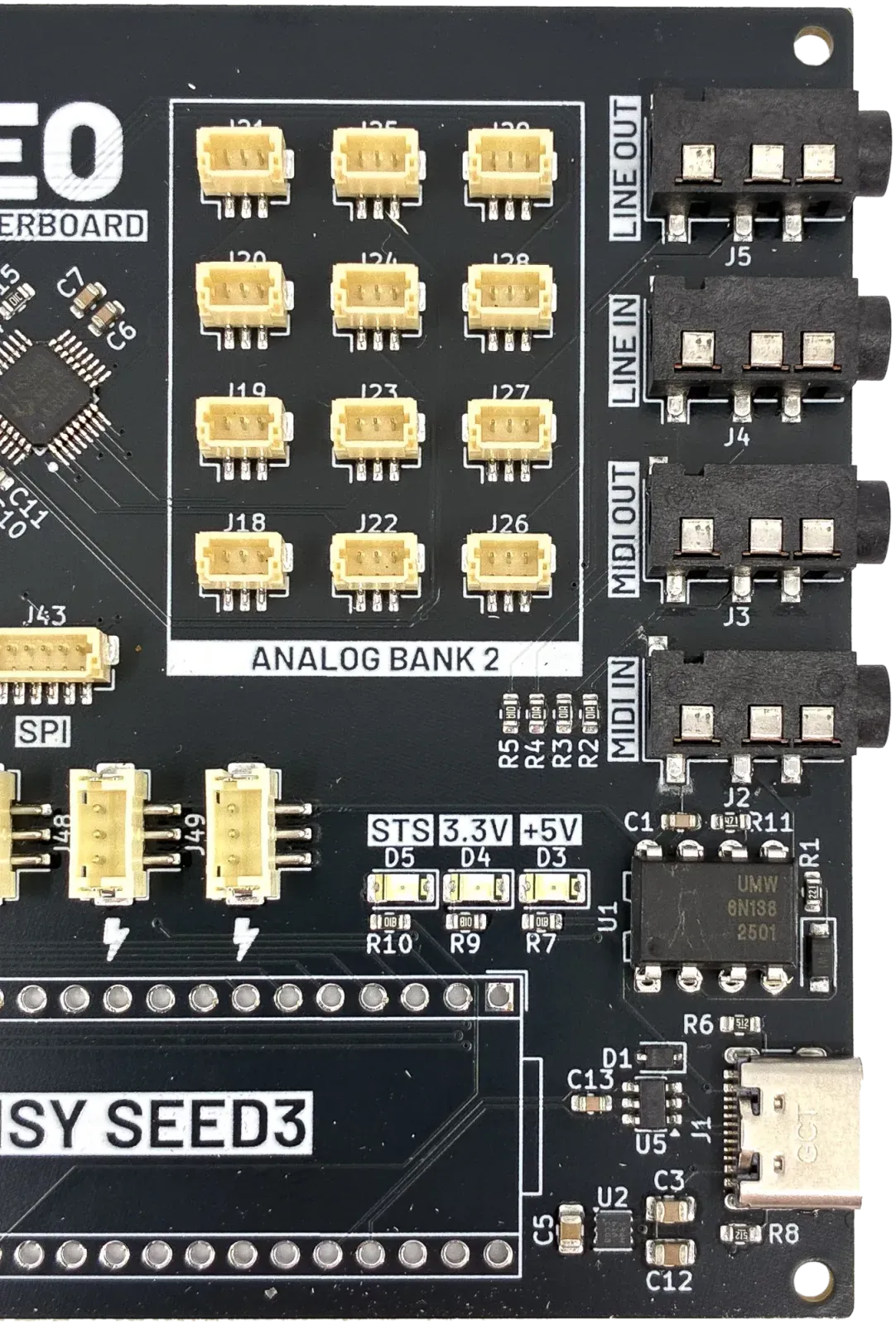
Prototype— panel I/O — the USB-C here is power only · photo -
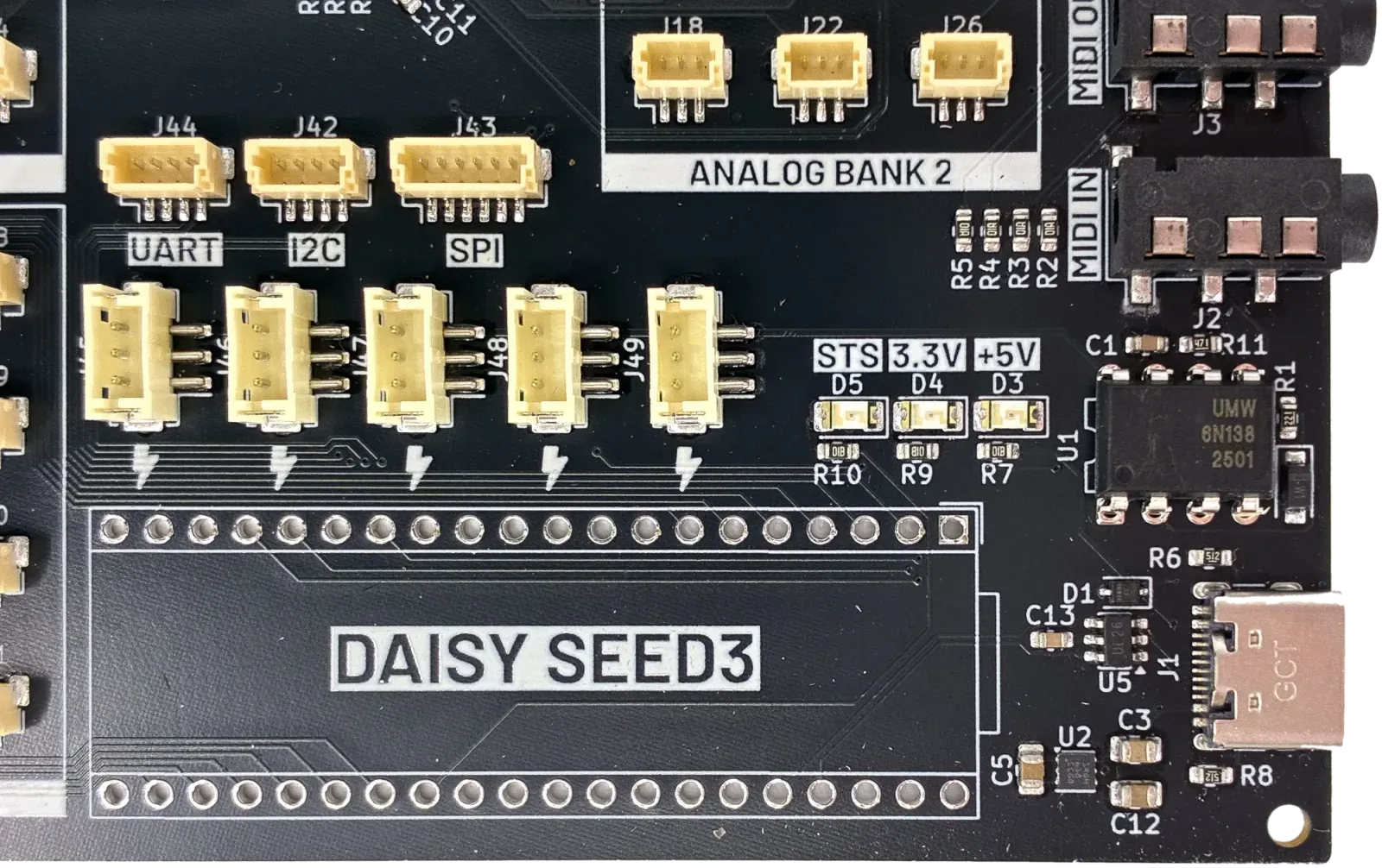
Prototype— the Daisy Seed footprint and bus headers · photo -
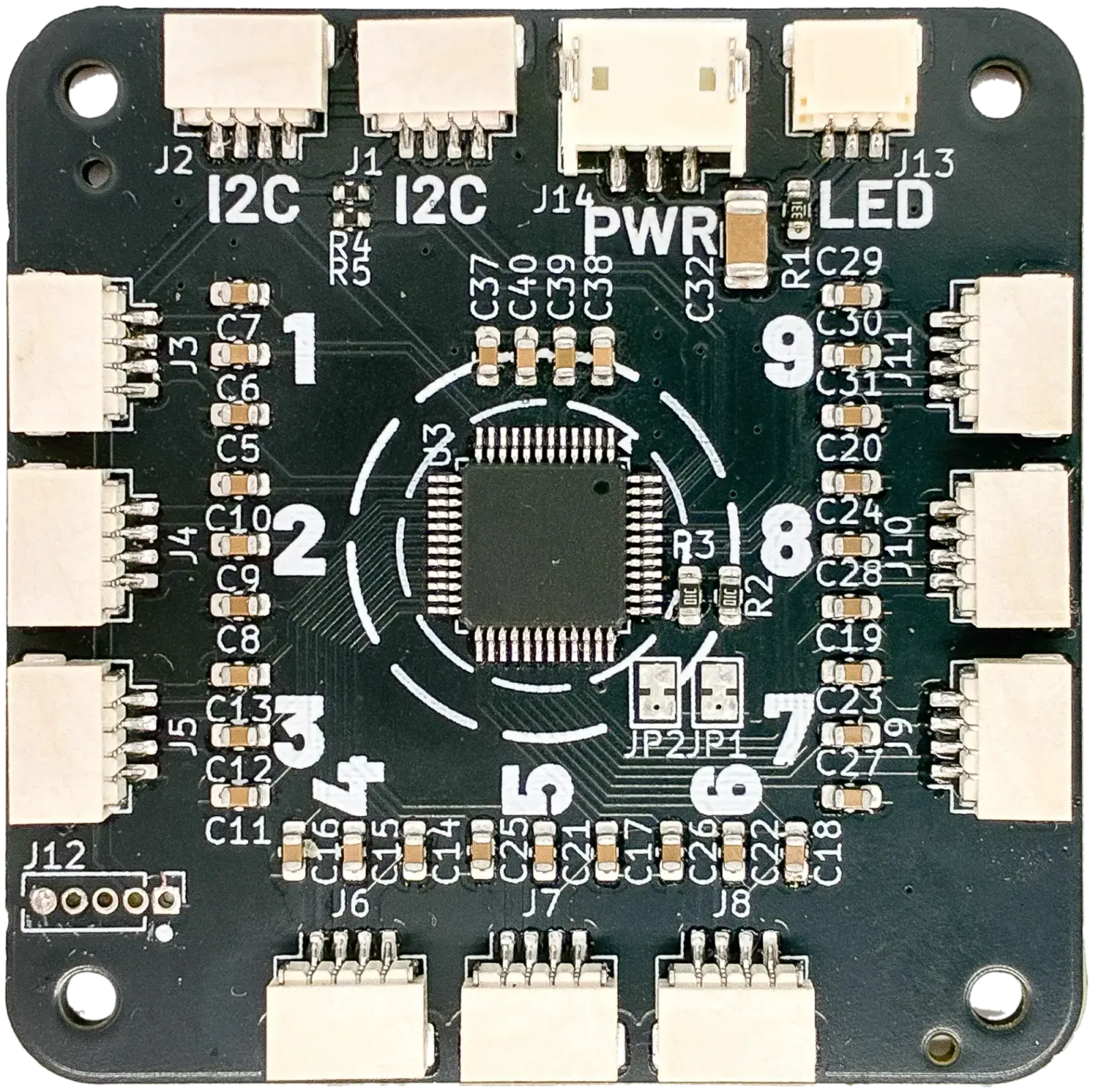
Prototype— rodeo-encoder-hub — retired in Rev-B · photo -
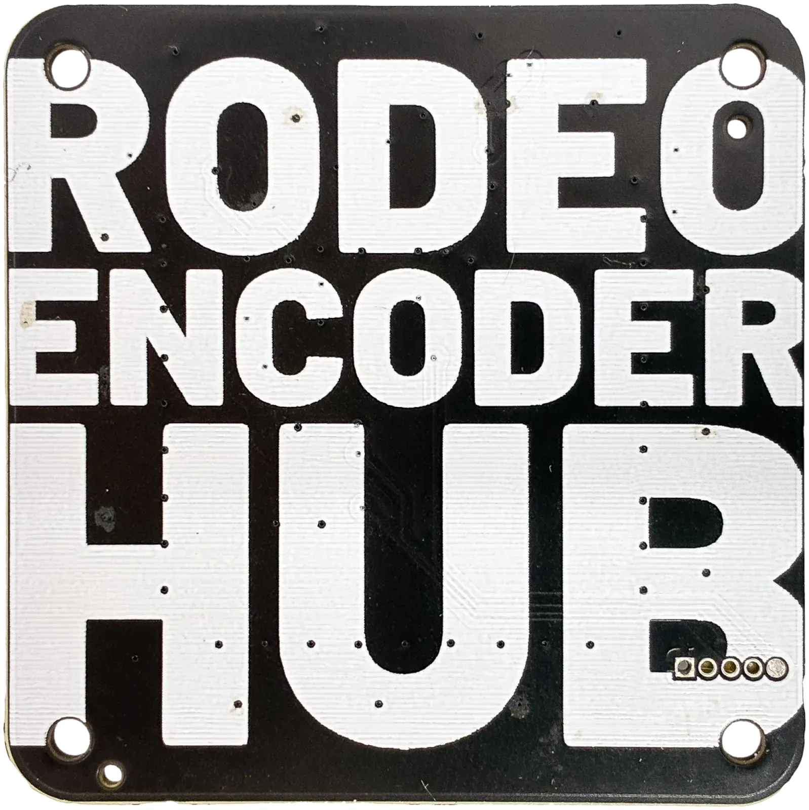
Prototype— the hub’s reverse, with its address jumpers · photo
Its satellite
rodeo-potentiometer
The simplest board in the family, and the only one that survives the Rev B redesign unchanged. The general-purpose I/O connectors deliberately use the pinout this board already has, so a single pot drops onto any analog-capable connector without an adapter. Use it where one control does not justify a satellite.
- connector
- 3-pin JST SH: GND, wiper, supply
- Rev B fit
- plugs into any analog-capable I/O connector
- electronics
- passive — one RC filter
What changed
And why Rev-B is a different board
Not a tidy-up. Building Rev-A and living with it changed what the platform should be, and the changes below are the ones that cost something — pins, parts, or a connector that no longer fits.
-
Analog inputs
Rev-A24 channels at 16 bits, from two converters soldered to every board
Rev-Bthe Seed’s own converter across eight I/O connectors; the 16-bit bank becomes an optional board
Every build paid about nineteen dollars for converters whether it needed them or not. Satellites cover ordinary knobs, so the precision bank became opt-in.
-
Audio
Rev-Aone codec, in and out
Rev-Ba second codec on the pins the converters vacated — four in, four out
The freed pins were worth more as audio than as analog inputs that satellites could supply instead.
-
Growing a panel
Rev-Aone cable per control, back to a motherboard channel or an I²C hub
Rev-Bsatellites chained together, each reading its own controls
Controls stopped being bounded by the motherboard. Position in the chain is the address, so there is nothing to configure and no respin when a panel grows.
-
USB
Rev-Apower only — the data lines went nowhere
Rev-Bdata through the power board: USB-MIDI, USB audio and firmware flashing
The most-checked spec on the Rev-A board, and the one most worth fixing.
-
Power
Rev-AUSB-C in, straight to a regulator — tethered to a wall for as long as it runs
Rev-Ba 1S Li-ion battery with a charger, power path and fuel gauge on the motherboard
Rev A had no battery of any kind. Rev B charges over USB-C and keeps charging with the switch off, which is the difference between a thing on a bench and an instrument you can pick up.
-
Jacks and MIDI
Rev-Aon the motherboard
Rev-Bdaughterboards on a rear rail
A smaller host board, and connectors a build does not need are connectors it does not pay for.
Want the real one?
Rev-B goes to Kickstarter in January 2027. Join the waitlist to hear first, and to watch the boards come back from the fab.